Design!
- Linda Mao
- Jan 27, 2022
- 4 min read

Once the team had a good concept of our goals with each subsystem, we started getting busy with designing the system!
First, let's take a look at the compression and heating system.
Heating and Compression
The heating and compression systems were the first to be integrated due to its relative simplicity.

The heating subsystem aims to dilate blood vessels in the hip musculature to increase circulation, which improves mobility and reduces pain. This is accomplished by a far infrared heating pad which provides deep tissue heat penetration and long lasting effects. The heating pad has three adjustable modes to provide a low, medium and high heat for pain relief and is suggested to be turned on for three, 30 minute sessions throughout the day.The graphene heating pad is insulated with non-woven fiberglass which reduces conduction heat transfer, decreasing the risk of burn.
The compression subsystem aims to decrease pain and encourage mobility, by reducing swelling and promoting venous return. The compression subsystem applies a pressure gradient between 50-60 mmHg to the extremities of the lower body. Pressure applied is highest at the feet and uniformly decreases as the the gradient progresses upwards. Among graduated stockings that can be purchased without prescription, the Sigvaris Natural rubber 505 is an available compression stocking that meets the engineering specifications laid out for the subsystem. Our team has purchased a set and are integrating it next with the heating subsystem.
Offloading
Our talented mechanical team members put their brains together and developed a novel 4-bar - back support offloading system.

The upper body system will provide a secure platform for the upper body to be loaded. Though the armpits will take majority of the force, there is a need for a back support to provide a base for the armpit supports. The back support will allow us to route the actuated linkage such that it doesn’t interfere with the patient’s range of motion when walking. In the design of our device, our actuation system will only provide approximately 5% of body weight force on either side.

The mechanical linkage between the foot and upper body consists of two stacked 4-bar linkages which provide independent vertical and planar motion between the torso and leg.

The attachment between the offloading mechanism and the foot must allow for free rotation of the foot during the swing phase of gait. It must also keep the mechanism perpendicular to the ground during stance (when the foot is in contact with the ground and carrying weight). The mechanism achieves this by having a free rocker (shown in yellow) between the mechanism and the foot. When the foot (which will be attached to the green piece) contacts the ground, the rocker is constrained by the ground and remains perpendicular to it.
To actuate the system, linear actuators were selected to be placed in series with an extension spring on top of each linkage. By contracting the actuator, the spring will be extended to apply the force required such that the system can be vertically displaced. The pulley/cable system allows the actuator and spring to be freely placed, and is attached to the other side of the linkage. Extending the actuator will allow the spring to retract back to its natural state, in which the linkage system will be free to move. By having the spring in series with the actuator, the actuator would not need to be constantly turned on since the spring will produce the required force passively, with the actuator being used to move the spring.

In order to detect gait, 2 methods of gait detection were combined and used. IMU sensors are known to be highly accurate in detecting gait - looking at the acceleration graph alone, heel strike can be seen at the highest peak while toe-off occurs at the second highest peak. This allows for accurate gait detection and prediction throughout the gait cycle. The IMU can be mounted at a combination of any 2 of the hip, knee or shin. On the other side, force sensors offers a very direct way of figuring out when heel strike happens and the foot is carrying weight. By mounting it at the bottom of the foot, it can detect force directly between the foot and ground.
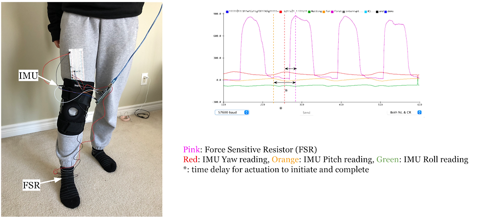
We did a couple of low fidelity characterization tests using an IMU and a force sensitive resistor (force sensor) to determine the required actuation speed. We mounted the FSR at the bottom of the heel such that it will detect heel strike, and tested the IMU at a couple of spots that research papers have had the highest accuracies in right image is a plot from the Arduino plotter where pink is the FSR reading, and the red/orange/green lines are the yaw/pitch/roll readings from the IMU peaks in each of these lines indicate heel strike. This test was really helpful in 2 ways: it provided us initial validation that the design for the gait sensing system does work, and second, gives us the speed spec we need for the actuator
the delay between the IMU readings and the FSR readings is the time we have for actuation to initiate and complete.
With all the design and some initial testing done, the team started to get to work with the build! TBC in our next post...


Comments